Electrical
Given the necessary sensor suite to complete the course, the electrical design of the TRACBOT21 was a critical component of the project. he electrical design was broken down into several subsystems, including power distribution, drive train, swivel and deposit servos, beacon sensing, line sensing, and the inertial measurement unit.
Power Distribution
Our robot was powered by two 7V2 battery packs attached in a series configuration to provide a total of 14V4. Several voltage regulators were used in order to manage power disribution to the rest of the robot:
- Two 12V regulators in parallel to the drive train (using multiple increases acceptable drive train current draw)
- One 12V regulator to the Arduino Uno
- One 5V regulator to the Servos
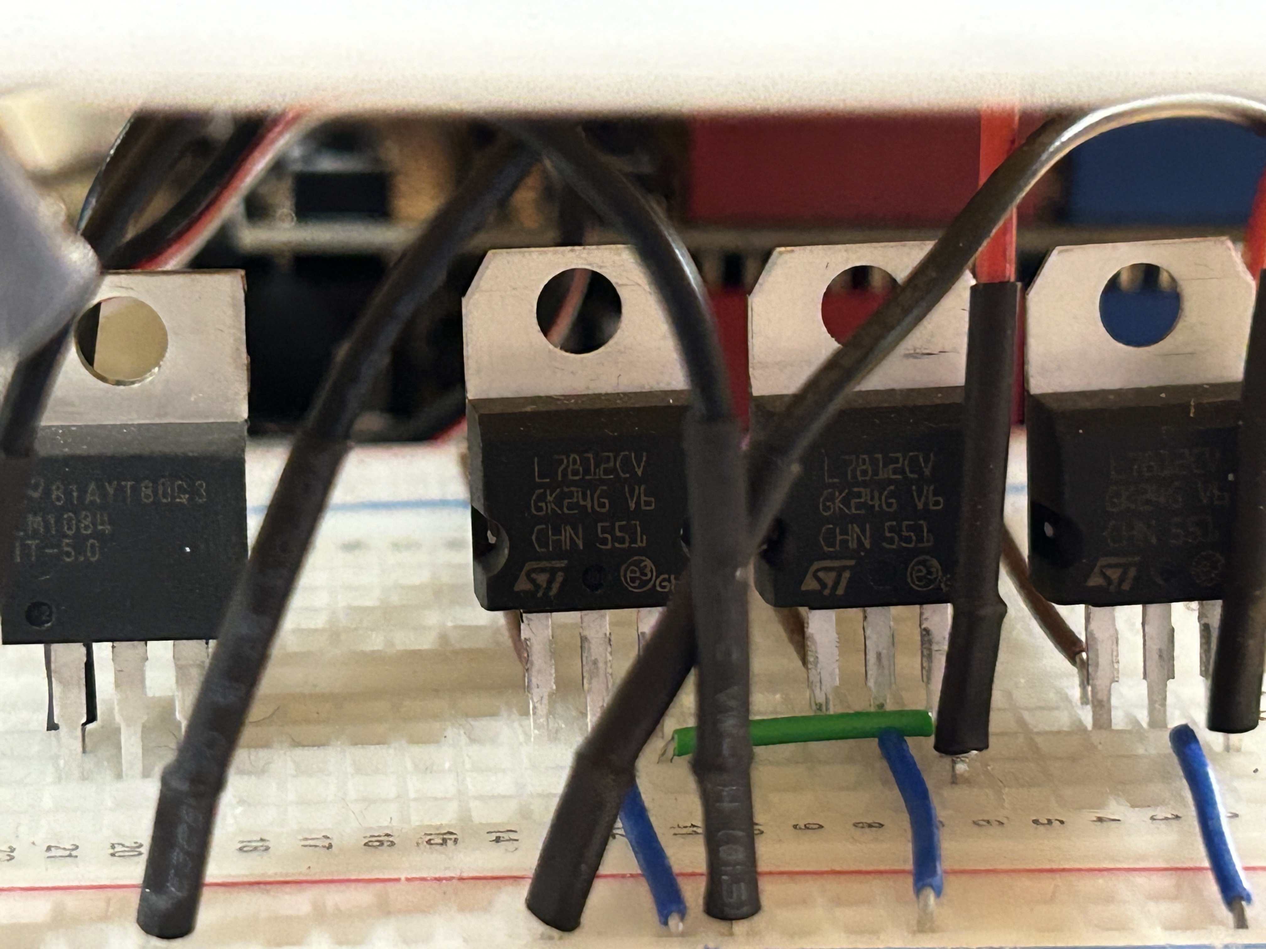
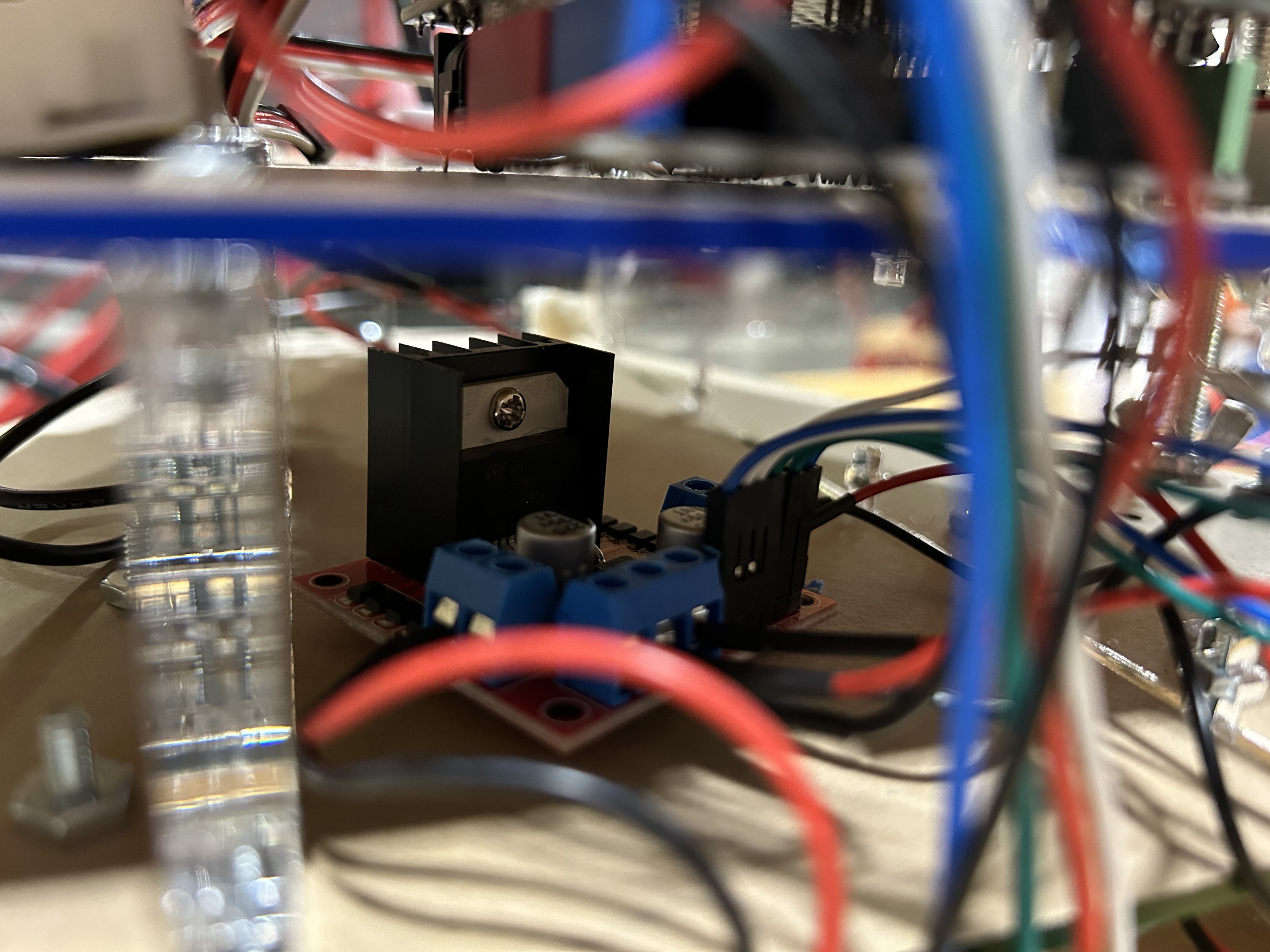
The 12V regulator used was the L7812, and the 5V regulator was the M1084. All were attached to the 14V4 supply; however, a potential improvement here to reduce wasted energy would be to supply the 5V regulator with a single 7V2 battery to reduce the voltage drop.
Drive Train
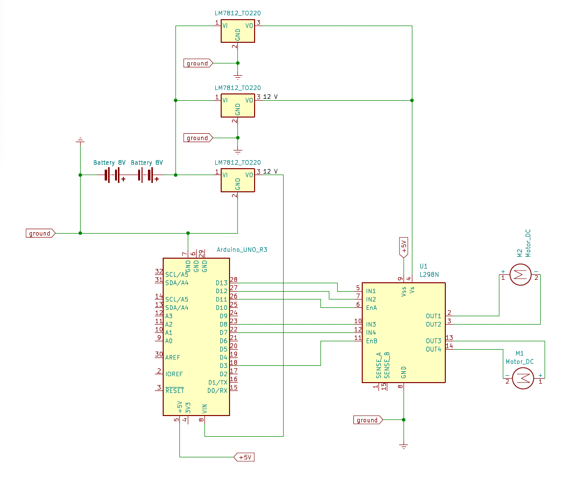
The drive train electronics were run off the L289N motor driver with a 12V power supply. Logic supply was taken from the Uno at 5V. Two 12V Greartisan DC Motors were selected for the drive train, and a the 100RPM configuration was chosen as this provided a good balance between maximum speed and speed range. Initially we selected the 200RPM configuration, but ultimately found that the minimum loaded speed was too high to enable precise turning. Luckily, this vendor has many different options with the same motor geometry, making it easy to iterate without redesigning the motor mount assembly.
Both motors were driven by a PWM signal to the enable pins for speed control. The pins used were specifically chosen to be on the same hardware timer (ITimer2) to improve consistency between the motor behavior.
Swivel & Deposit Servos
The robot uses two servo motors:
- A DS3218MG high-torque servo to move the ball-deposit swivel, which is also used to orient the IR beacon.
- A micro servo to release balls from the swivel tube.
In an early design, both servos were driven using PWM signals generated from the Arudino. However this system proved to be unreliable, likely due to the use of the Arduino hardware timers for other tasks. The servos would jitter and fail to maintain a consistent position.
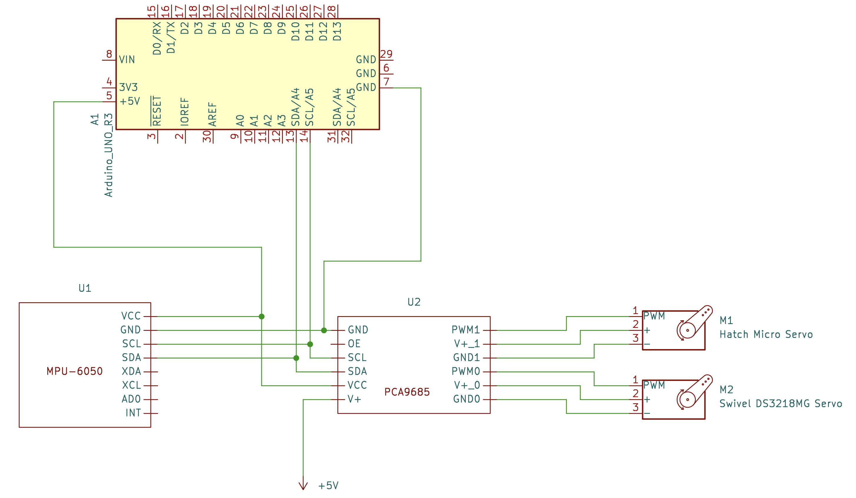
Instead, we elected to use a PCA9685 I2C servo driver breakout board provided by a member of our team. This driver allows up to 16 servos to be controlled independently, with an onboard clock providing the timing signal for PWM frequency and duty cycle. The PWM duty cycle, which determines servo position, is set by I2C message and is maintained until a subsequent message is received.
Both servos are powered by a dedicated 5V regulator.
Beacon Sensing
The beacon sensing subsystem is based on an LTR-3208E phototransistor sourced from our lab kit mounted on the robot swivel. The overall purpose of this circuit is to provide an analog voltage level corresponding to the strength of the 3333 Hz beacon signal received by the phototransistor: this allows the robot to measure the direction of maximum received signal and thereby orient itself relative to the IR beacon.
Our original intention was to use the beacon both for determining initial orientation and for guidance as the robot moves between the contact zone, shooting zone, and ramp. This requires a circuit with extremely high dynamic range as the intensity of the beacon signal decreases with the square of the distance from the beacon. To address this, we designed a two-stage amplification circuit and intended to use an analog multiplexer to select between the output of the first amplifier, which provided moderate gain suitable for use close to the beacon, and second amplifier, which further amplified the signal for use in the starting zone. However as the project progressed we elected to drop the requirement for beacon sensing close to the beacon and replaced the analog multiplexer with a mechanical switch: This allowed us to continue to use the moderate-gain setting for testing, and the high-gain setting for initial orientation.
The basic sections of the circuit are:
- A transresistive amplifier with offset voltage to convert the phototransistor current signal into a voltage signal.
- A DC-blocking filter with offset voltage.
- Two noninverting amplifier circuits, each with a DC-blocking high pass filter on the output.
- A mechanical switch allowing selection between the output of the first amplifier and the output of the second amplifier.
- A final low pass filter to reduce high frequency interference.
- A peak detection circuit, with reset, to provide a smooth analog output voltage to the Arduino.

A Python program was written to aid in calculation of the required amplification gains, cutoff frequencies, and component values in each stage of the circuit. The eseries library was extremely helpful for determining the best combination of resistor and capacitor values to meet gain and frequency specifications.
A video demonstrating use of the beacon sensor for initial orientation is provided in the Results section.
Line Sensing
The line sensing circuit utilizes three RPR220 IR reflective sensors. Reflective sensors contain both an IR LED and a reciever to measure the reflectance of a surface. If there is black tape, the sensor reads a low value which can be used to detect that the robot is above a line.
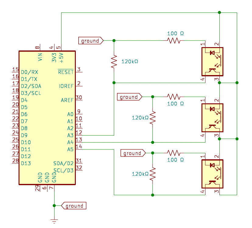
Three sensors were used primarily for robustness in the sensing capabilities of the robot. As documentation for the RPR220 was quite limited, the resistors were tuned experimentially to provide a large voltage range in the measurements. Each sensor was connected to an Uno analog pin. This allows for the software to make a determination on if a line has been detected.
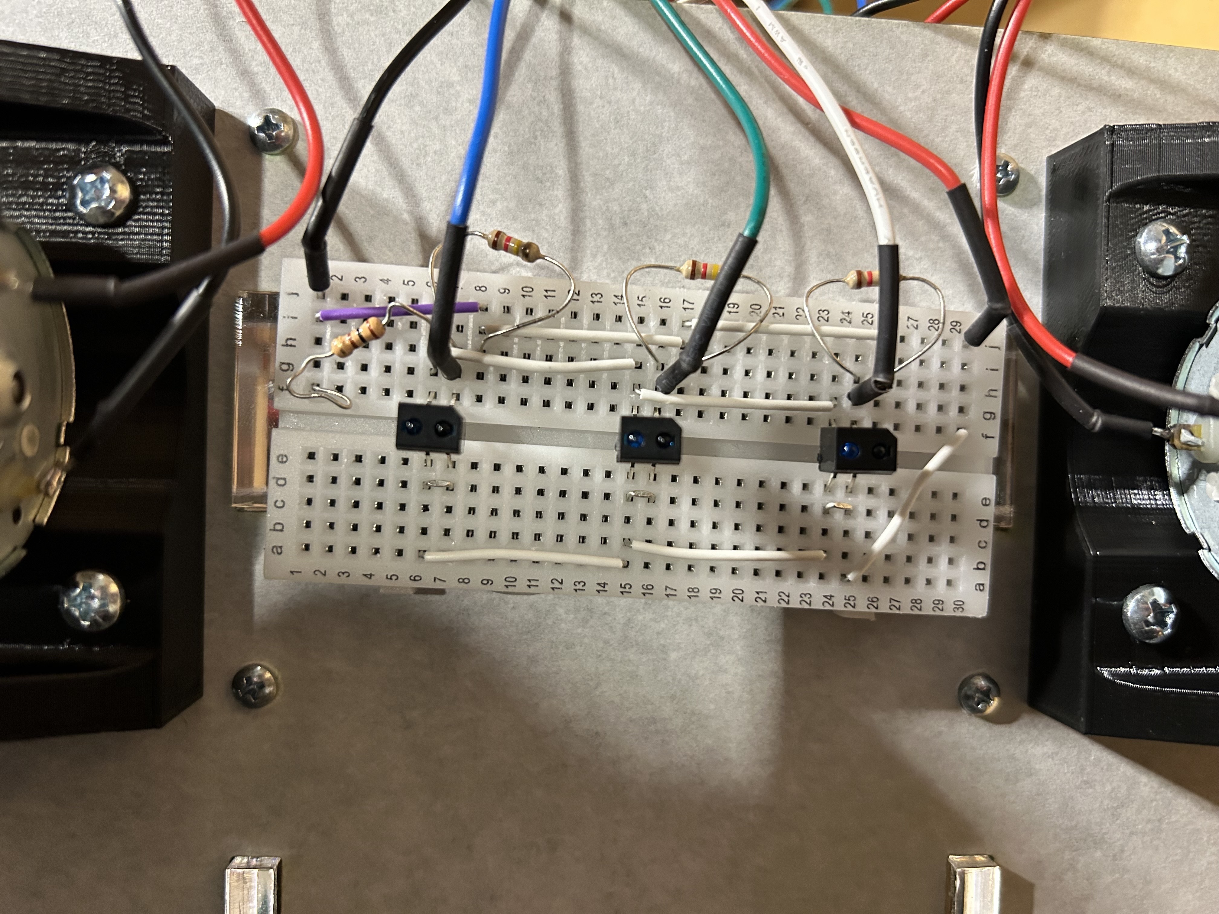
The casing surrounding the RPR220 made our line sensing quite robust and reliable in the presence of ever-changing external conditions. This is because nearly all noise sources were blocked, and we are able to consistently pick up the reflected signal off the ground.
Inertial Measurement Unit
The IMU selected was the MPU6050. This IMU is powered off of a 3V3 supply from the Uno and communicates with the Uno via the I2C communication protocal. This unit hosts three acceleratometers and gyroscopes to measure accelerations and angular velocities respectively. However, the only sensor that was actively used in the software was the +Z gyro, which allowed us to measure the robot’s rotation rate.
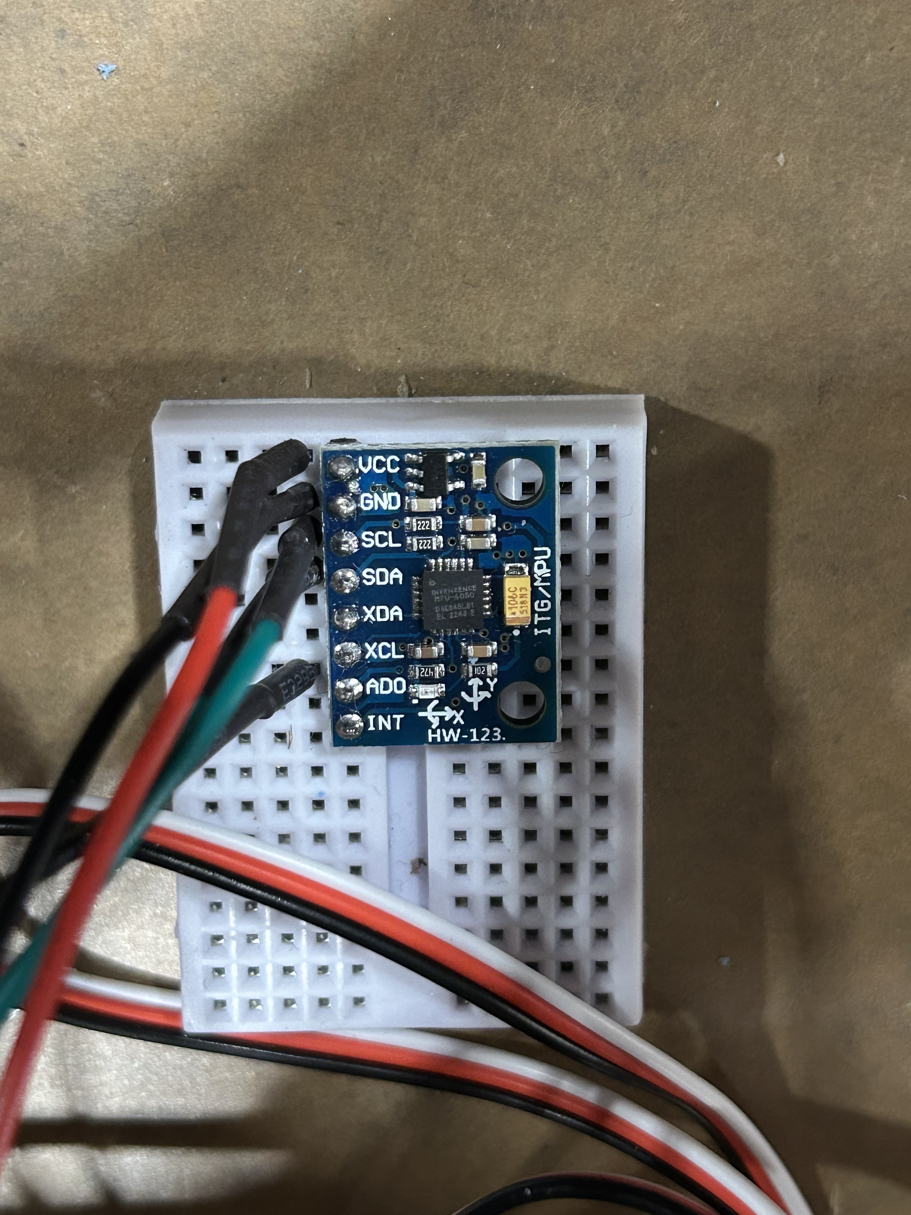
The IMU was provided with its own hardware timer (ITimer1) to ensure that its measurements could be processed and integrated with the highest available precision. More information on how the IMU measurements were used in the software is specified in the Software Design section.