Mechanical
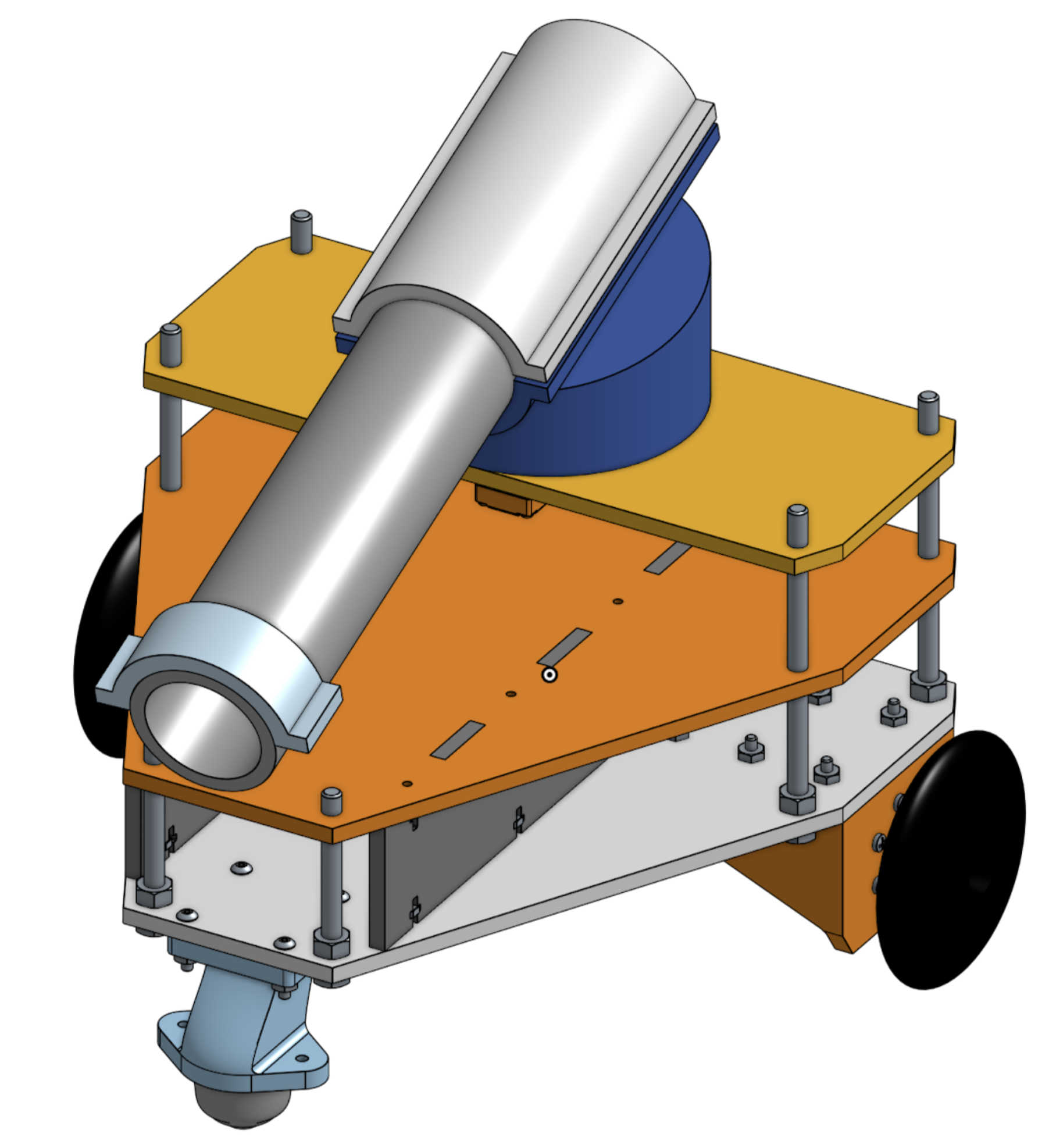
The overall design of the TRACBOT21 is shown in the render below. Next, we will go into the each of the mechanical components of the robot in detail.

Drive Train
The drive train is arguably the most important part of the robot, as the competition requires mobility and sensors depend on a working drive train. The drive train is composed of two DC motors, two wheels, and a caster wheel.
Initially, motor performance mismatch resulted in significant rightwards drift when attempting to drive the robot straight. This was remedied at first by a PI controller for forward motion. This controller was eventually abandoned in favor of the simpler application of a 5% bias to the right motor (i.e. if the left motor was being driven at 100 rpm, the right motor would be driven at 105 rpm in order to account for the motor bias and drive the robot straight).
Chassis
We opted for a relatively large and weighty chassis in order to ensure robot stability and allow for extra mounting space in the event of last-minute design changes, making our robot just smaller than the maximum dimensions specified by the project statement. We emphasized stability because we spun our dumping mechanism using a relatively powerful servo motor, and we wanted a stable, sturdy base that could withstand both strong internal torques as well as potential high-speed wall collisions. We designed our chassis in order to front-load mass above the two front drive wheels in order to ensure that our robot was capable of driving up the ramp without tipping backwards, and additionally ensured that the lower chassis plate had ample clearance above the wheels to ensure that no part of the robot would impact or scrape the ramp during transitions onto and off of it.
Dumping Mechanism
Our dumping mechanism consisted of a drain pipe purchased from Home Depot, cut to size and mounted to the robot via a 3D-printed rotating fixture. We designed our dumping mechanism for a 180 degree range of motion, such that at its neutral position (pointed towards the back of the robot) it could spin 90 degrees in either direction, and accordingly aim and shoot the balls into the shooting zone regardless of whether it was on Course A or Course B. The dumping mechanism itself was oriented by a servo motor, while another, smaller servo motor was positioned at the end of the tube to act as a hatch to hold and release the balls from the tube.
Interactive 3D Model
Our design is shown below in a 3D interactive fashion.